There’s a wide range of USB powered devices around an average tech enthusiast: phones, tablets, Raspberry Pies, flashlights and electronic cigarettes. My hand-held electric screwdriver can be charged from USB nowadays.
We can probably survive (or not) without our phones being constantly on. However, some of our USB gadgets rely heavily on uninterrupted supply of 5V input voltage: Raspberry Pies, dash cameras, smartphones used as CCTV, etc. They can be equipped with internal batteries and can withstand short-time power interruptions (like smartphones), but when it comes to battery-less devices (e.g. Raspberry Pi) or frequent power outages (dash cams in our cars), truly uninterrupted power is a must.
Of course, ready-to-go off-the-shelf standardized-certified products are always an option, whether it’s specialized UPS extension board for Raspberry Pi, Power Magic Battery Pack for dash cam in your car, or 110V UPS with USB charging port for pretty much any 5VDC/110VAC powered device. However, there’s a cheaper (and fun) way of putting a few simple components together achieving the same goal for a fraction of price.
In my case, I’m building uninterrupted power supply for Xiaomi Yi dashcam in my car. I’m using similar setup for Raspberry Pi running my home media center (I trip my 15A brakers way too often in my house).
Let’s take a look at what will we need for this 30-minutes project (all images are clickable):

- 2-channel DC 5V relay ($6.79)
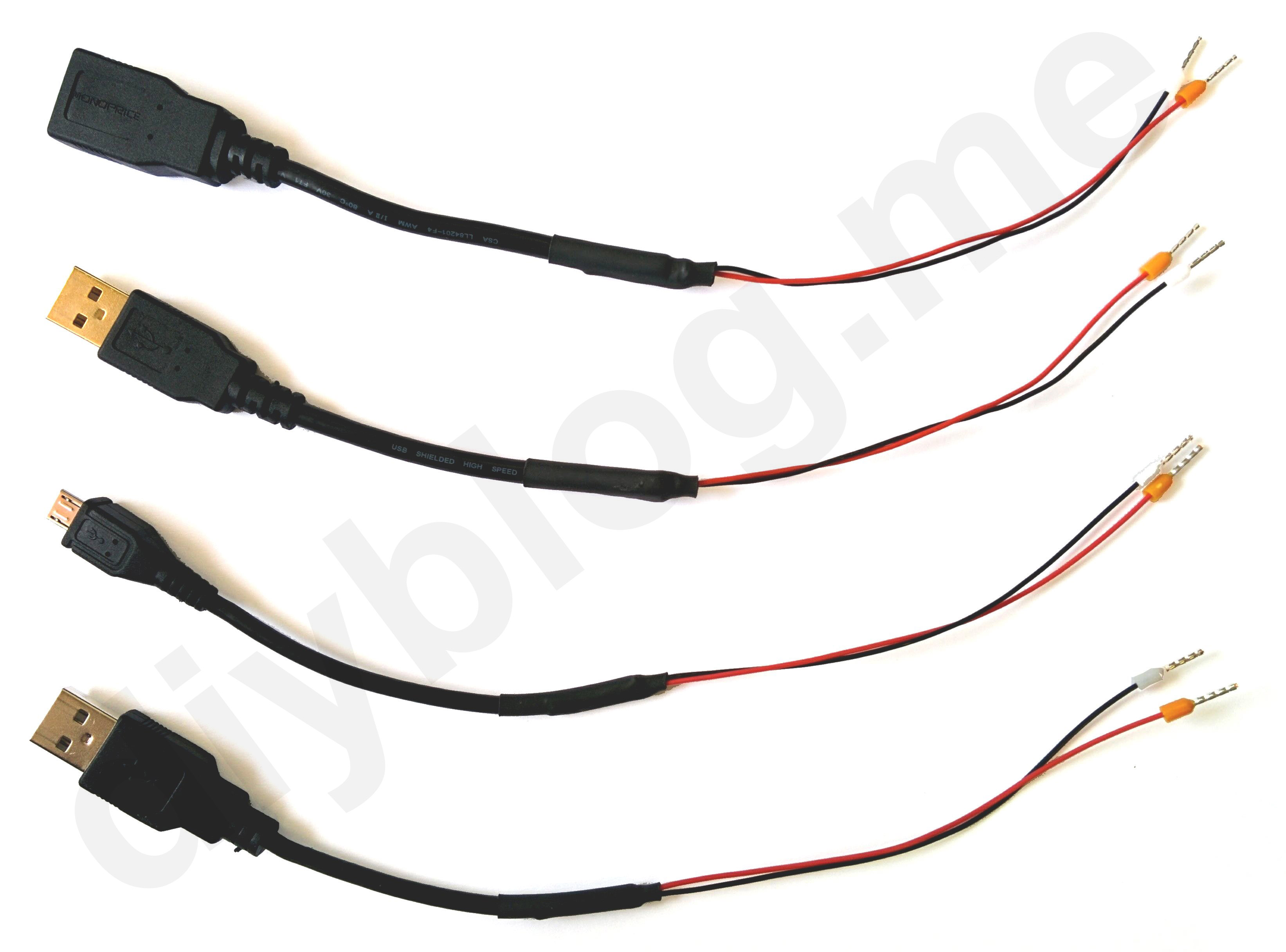
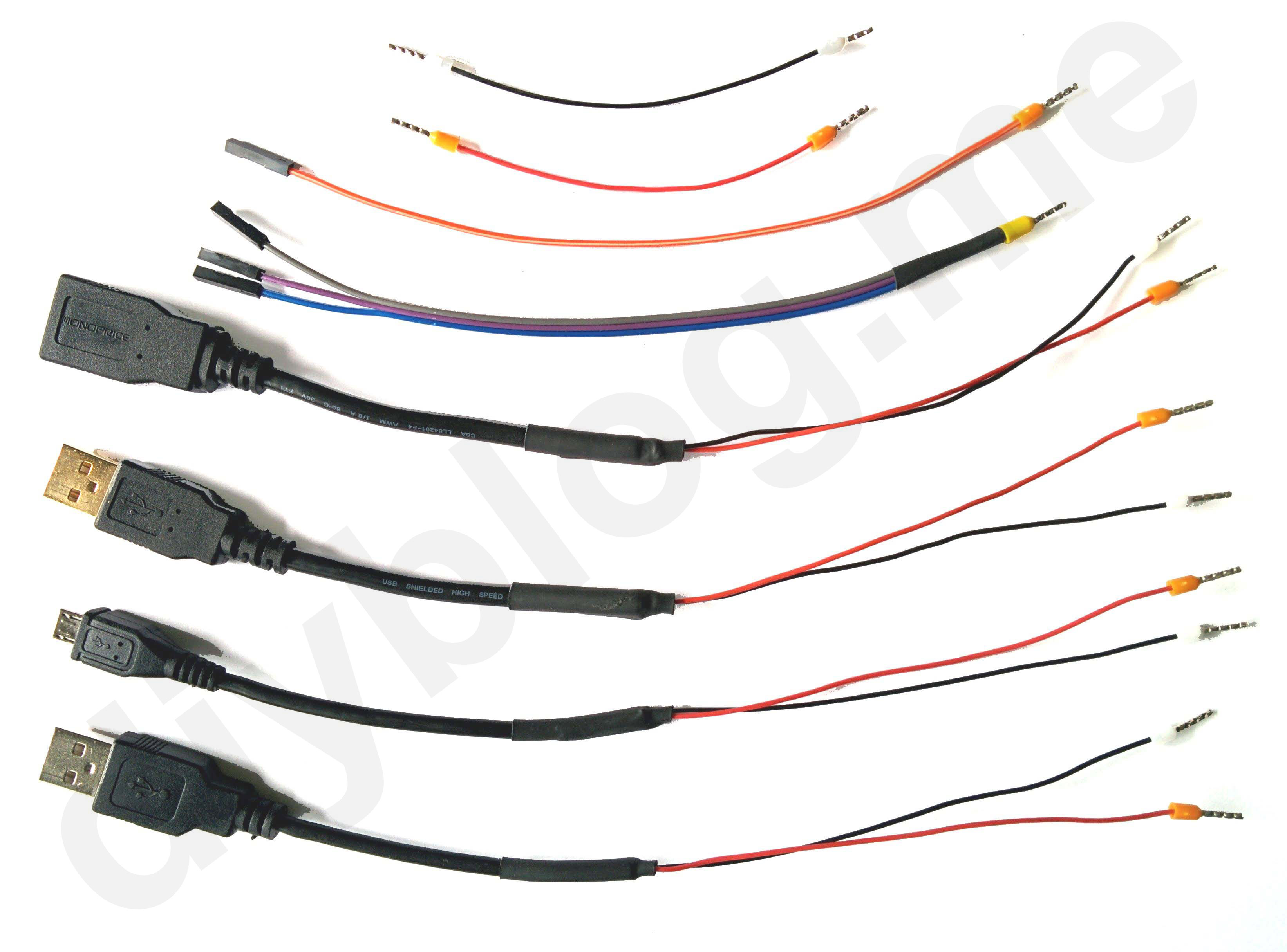
- USB extension cable ($4.12)
- Micro-USB charging cable ($5.26)
- 10,000 mAh power bank ($$21.99)
- Dupont Jumper Wires (pack of 120) ($5.99)
- 5-conductor lever-nuts connectors (pack of 40) ($9.95) (optional)
Your total is going to stay below $50, or if you have a power bank to reuse, below $25.
How does it work
The idea is to simply switch the USB power from normal source (wall plug power supply or 12V car USB adapter) to a backup (power bank). We also need to keep the power bank charged from the normal source, when it’s available. Hence, we need 2-channel relay: controlling both nominal source power line and backup power line.
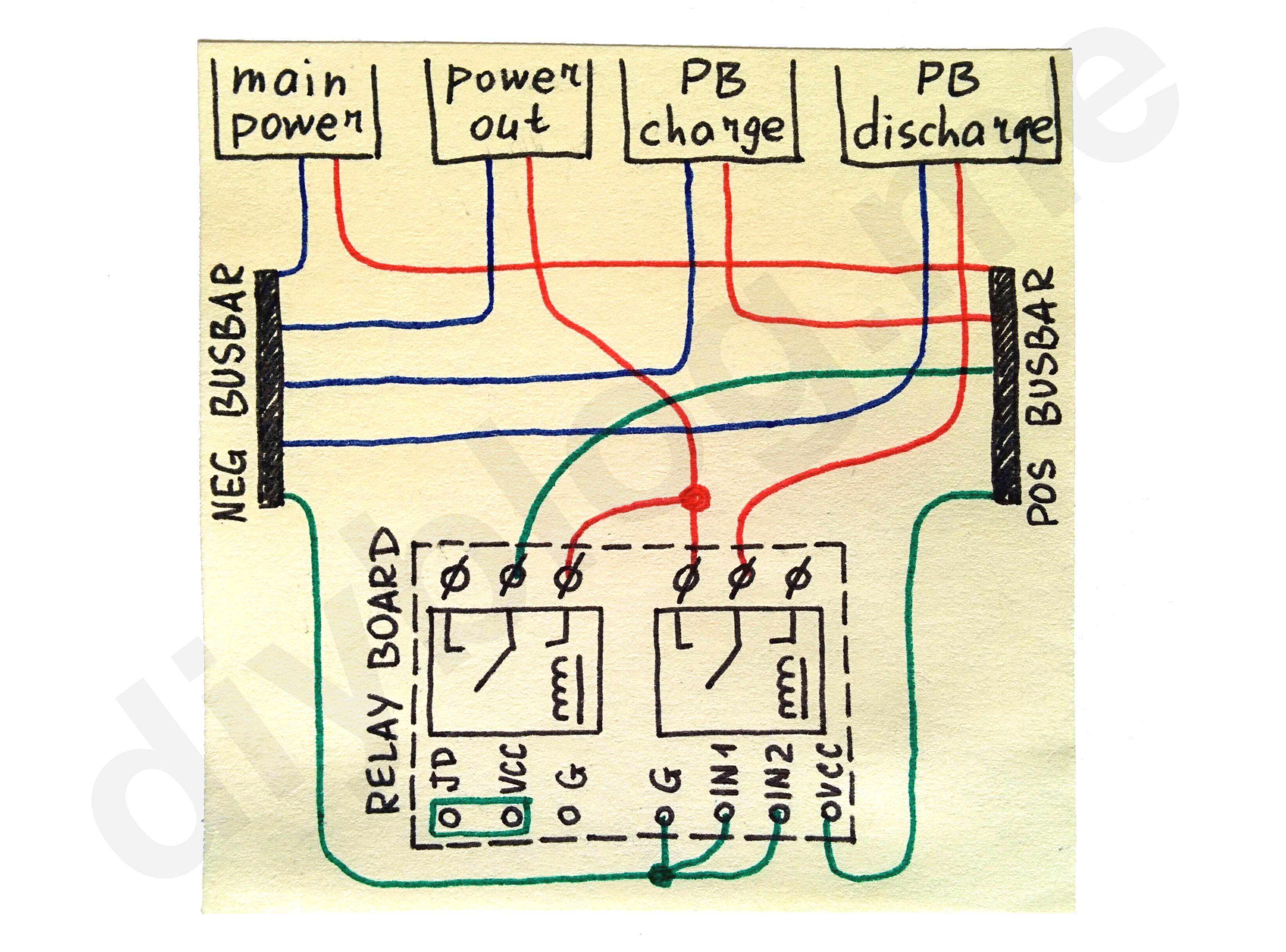
Schematic is so simple, it fits into one post-it sticker:
Cut, strip, crimp, repeat
We need to make four connections to the relay:
- normal power input
- backup power input
- consumer output
- power bank output
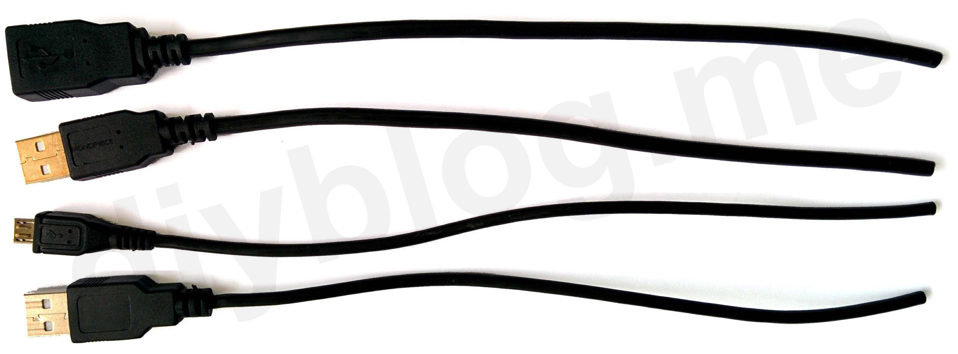
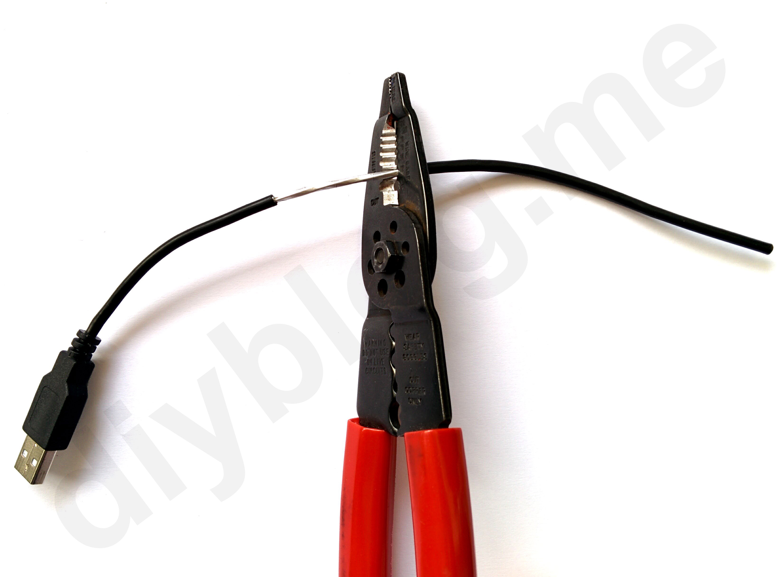
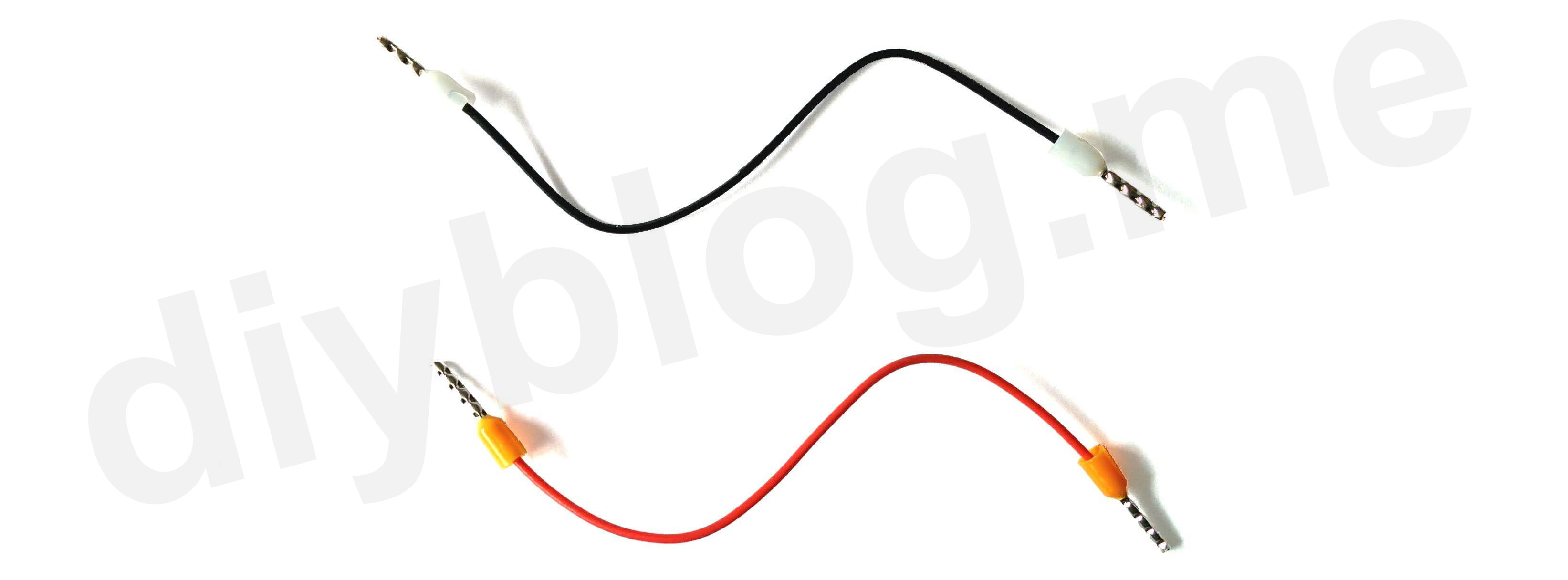
Simply cut tails from both cables, approx. 10” each.
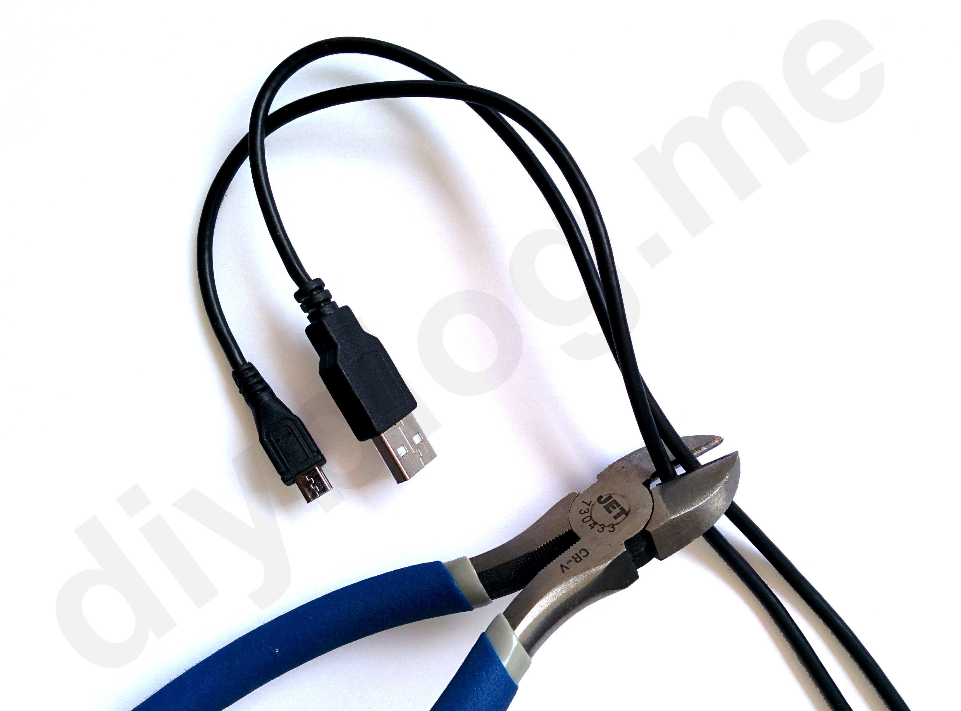
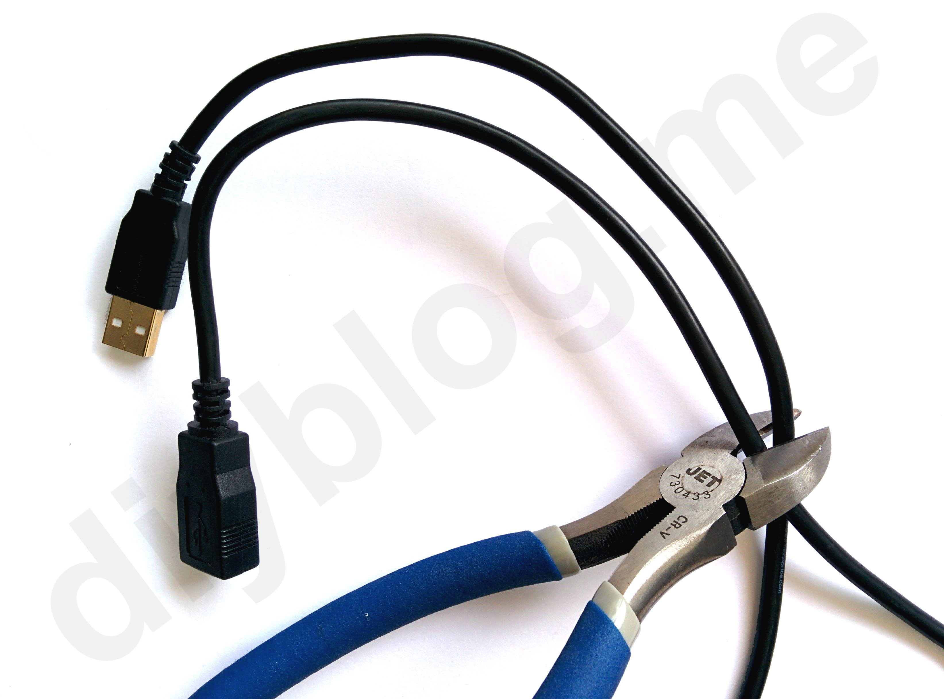
These cable tails will be connecting the relay with power source, power bank and our gadget (dash cam, in my case).
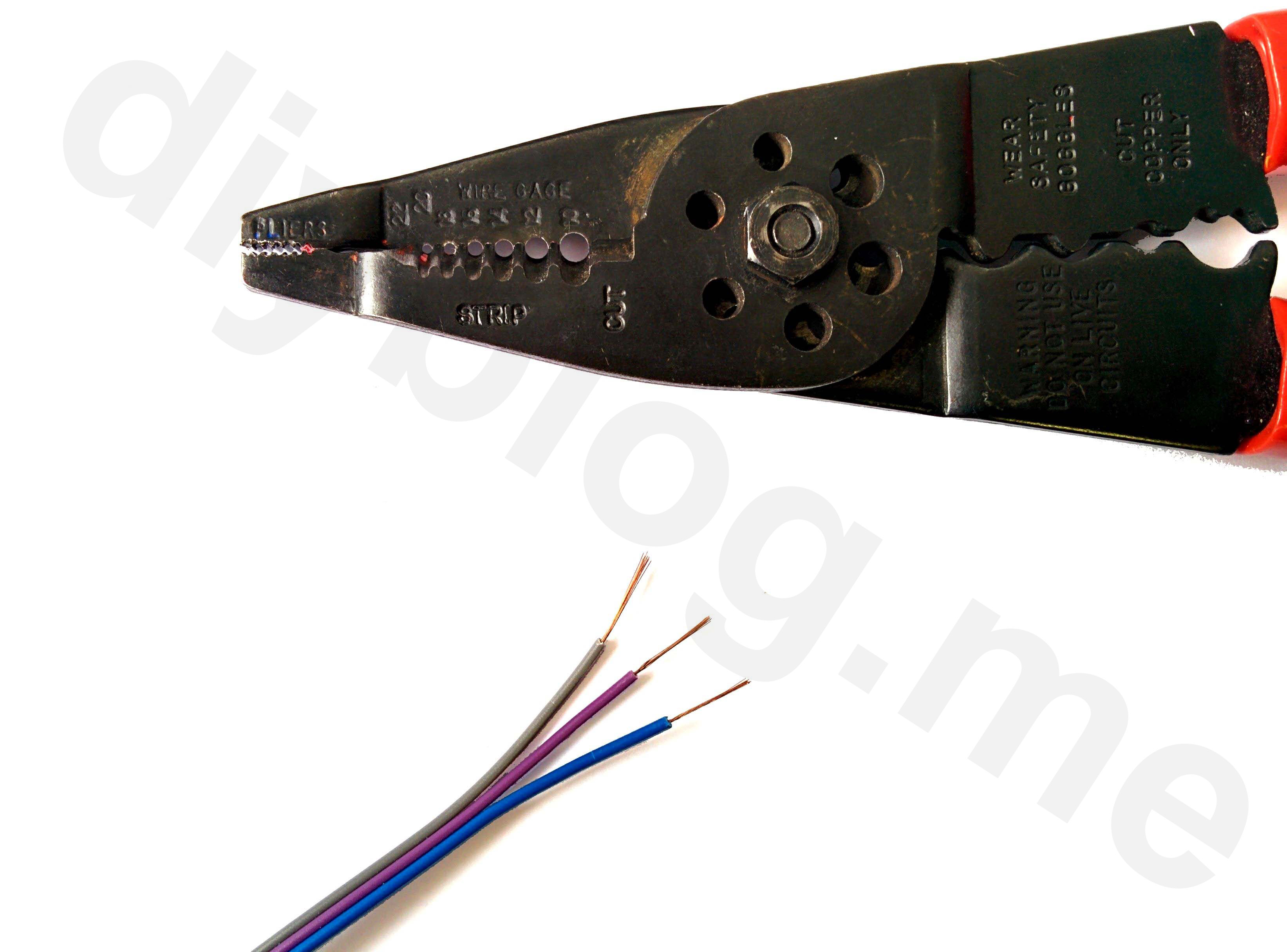
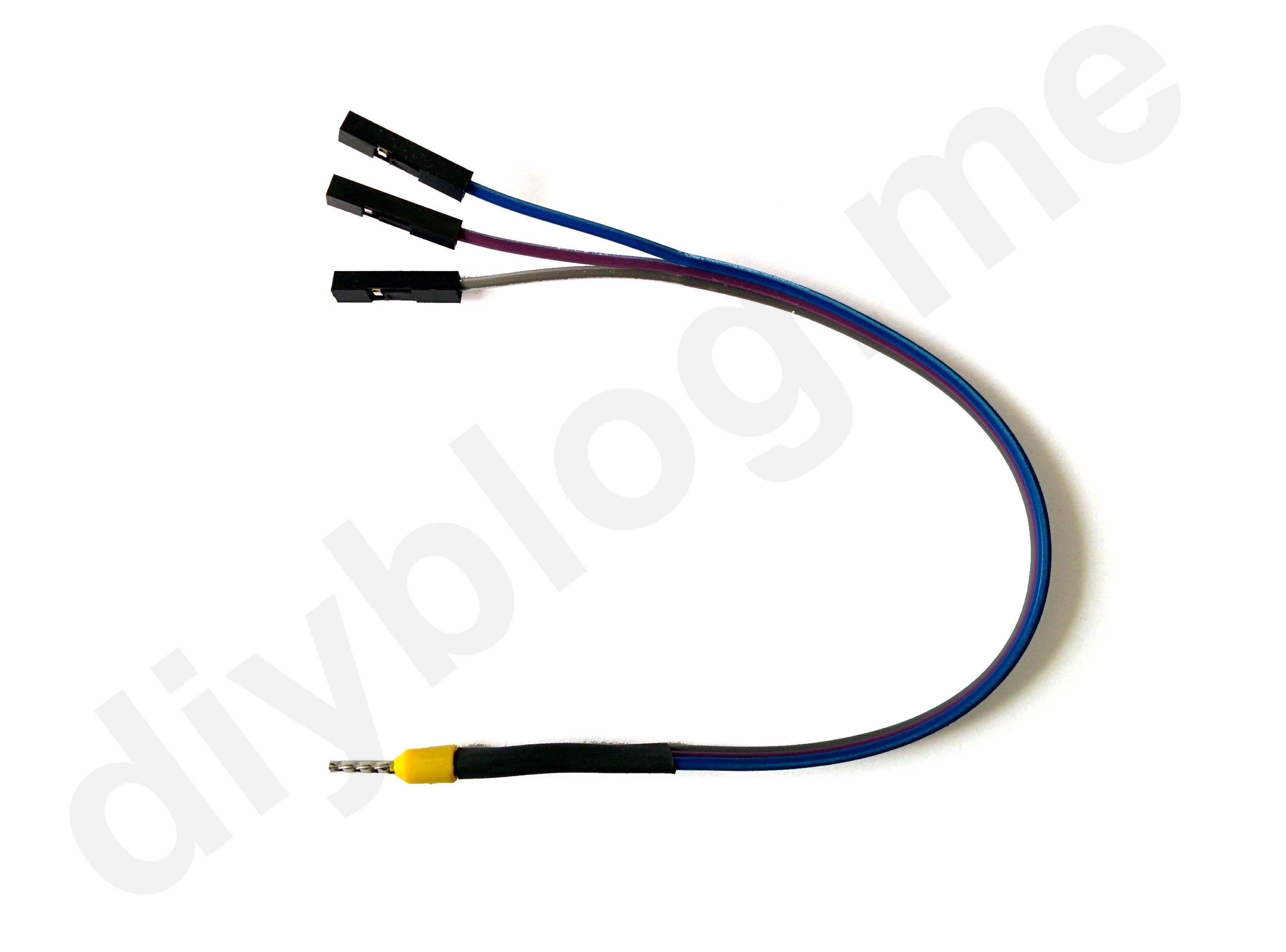
Now prepare the wires. Carefully strip the outer insulation first (wire stripper will be really helpful here).
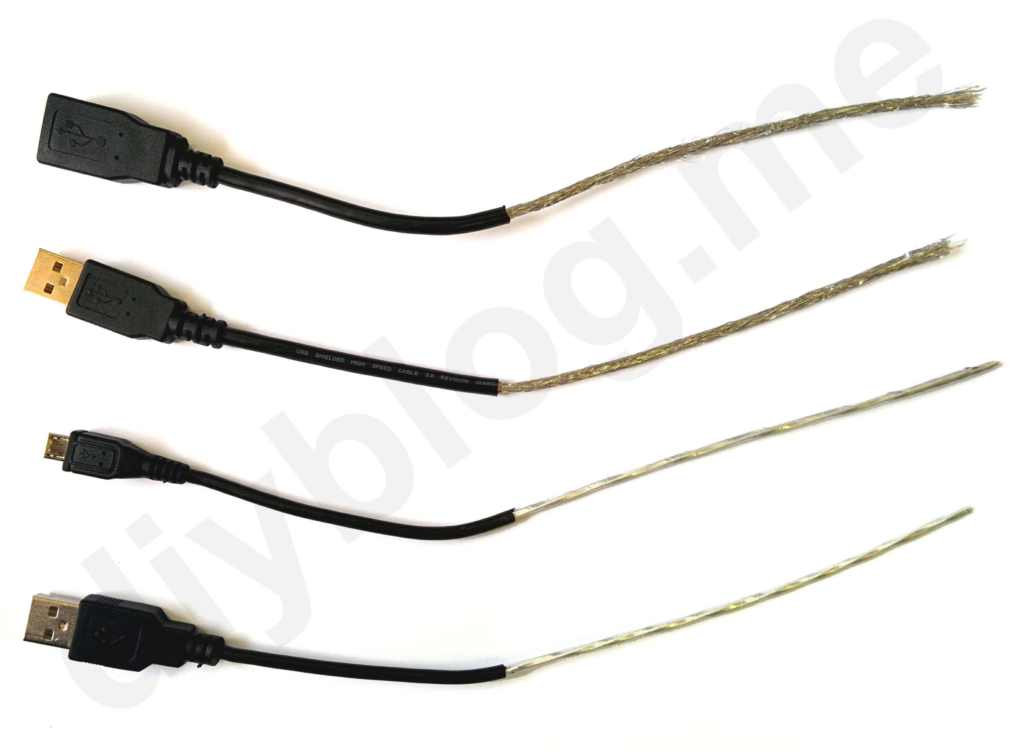
Now remove the shielding (foil or wire mesh wrapped around wires) and make your ends look tidy. We only need black and red wires (power), two other ones and the shield (uninsulated wire) can be removed or left under the heat shrink.
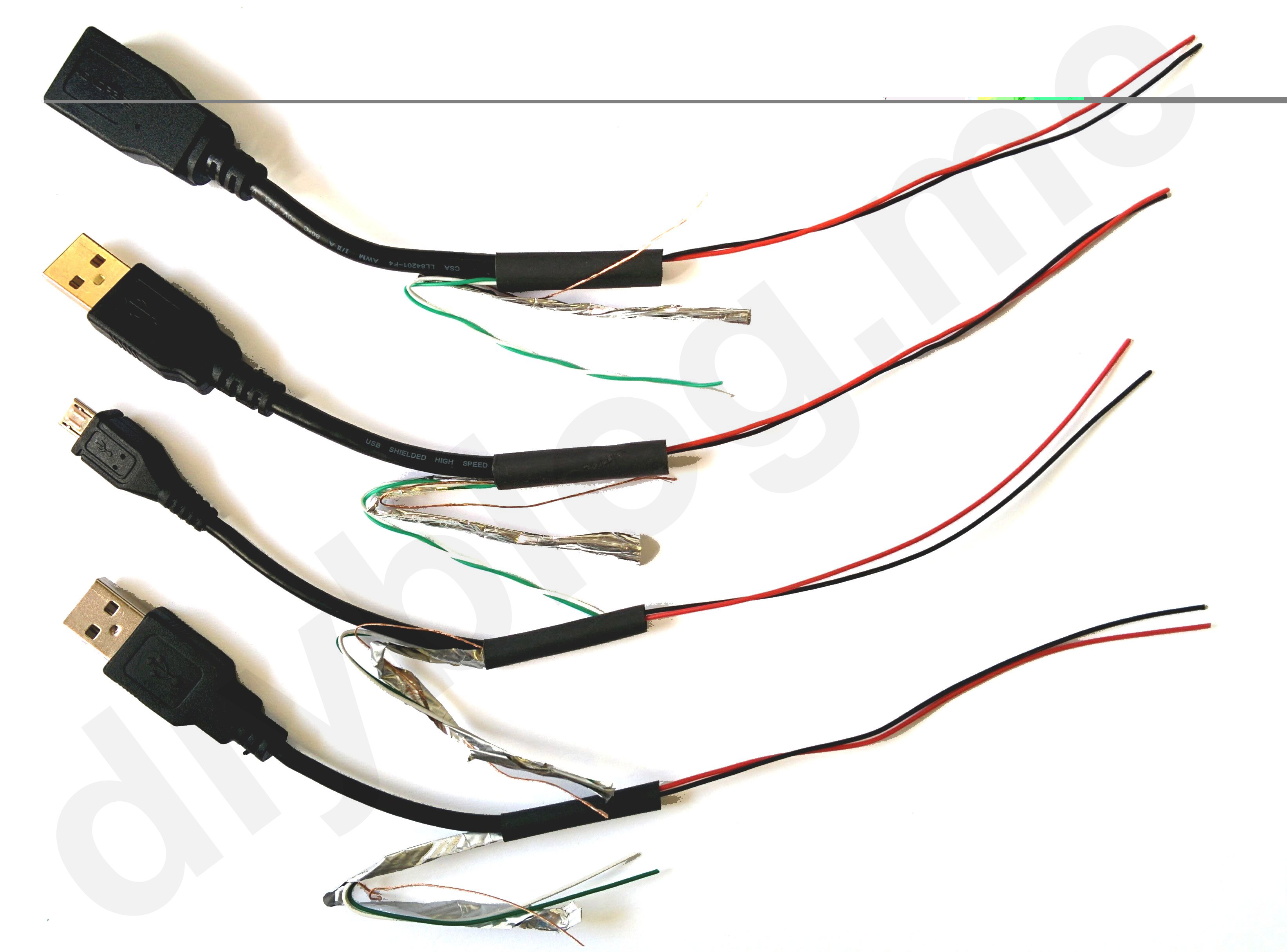
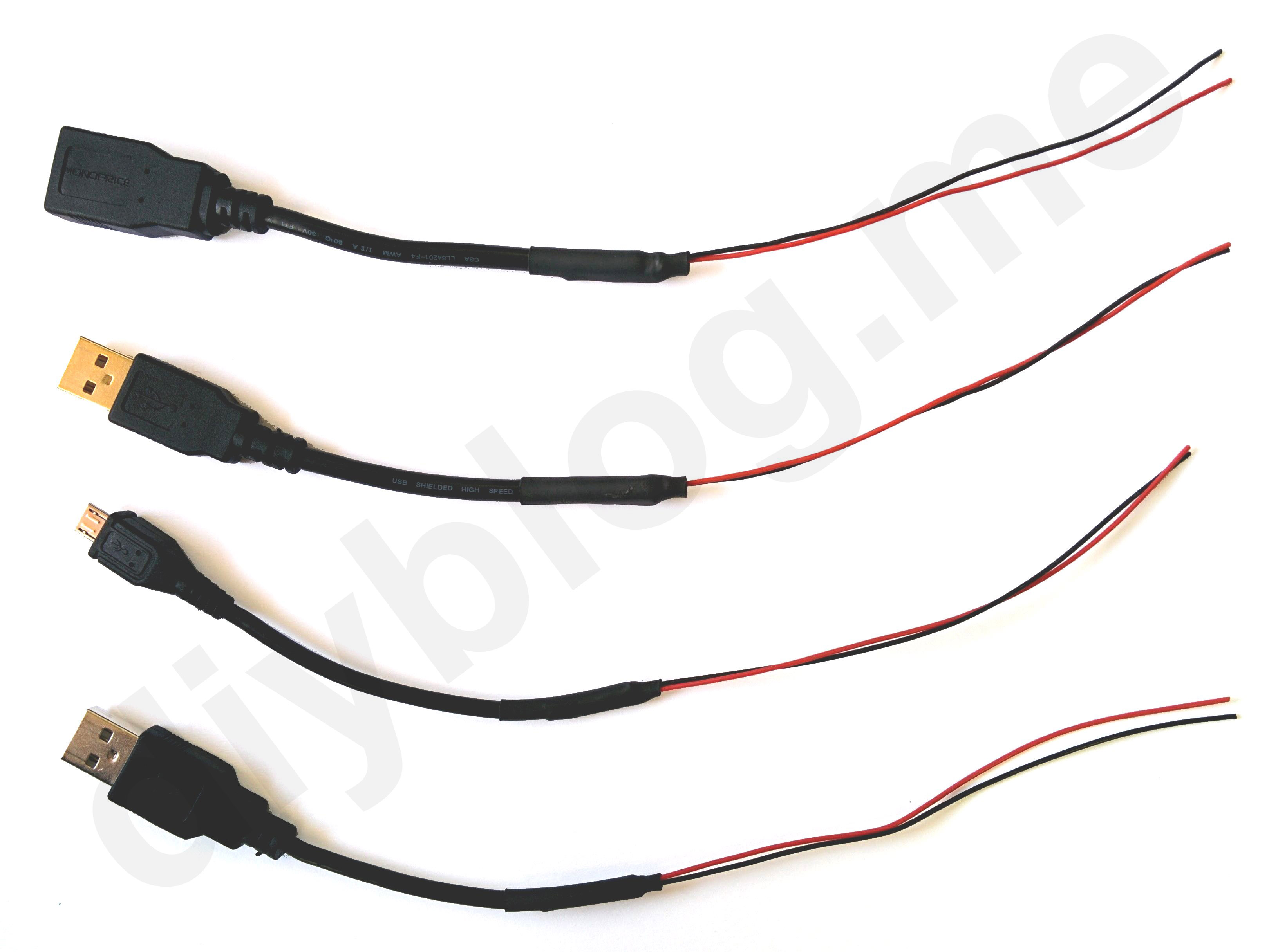
Now strip black and red wires. I’ve also crimped them for better connection, you can use some solder as well.

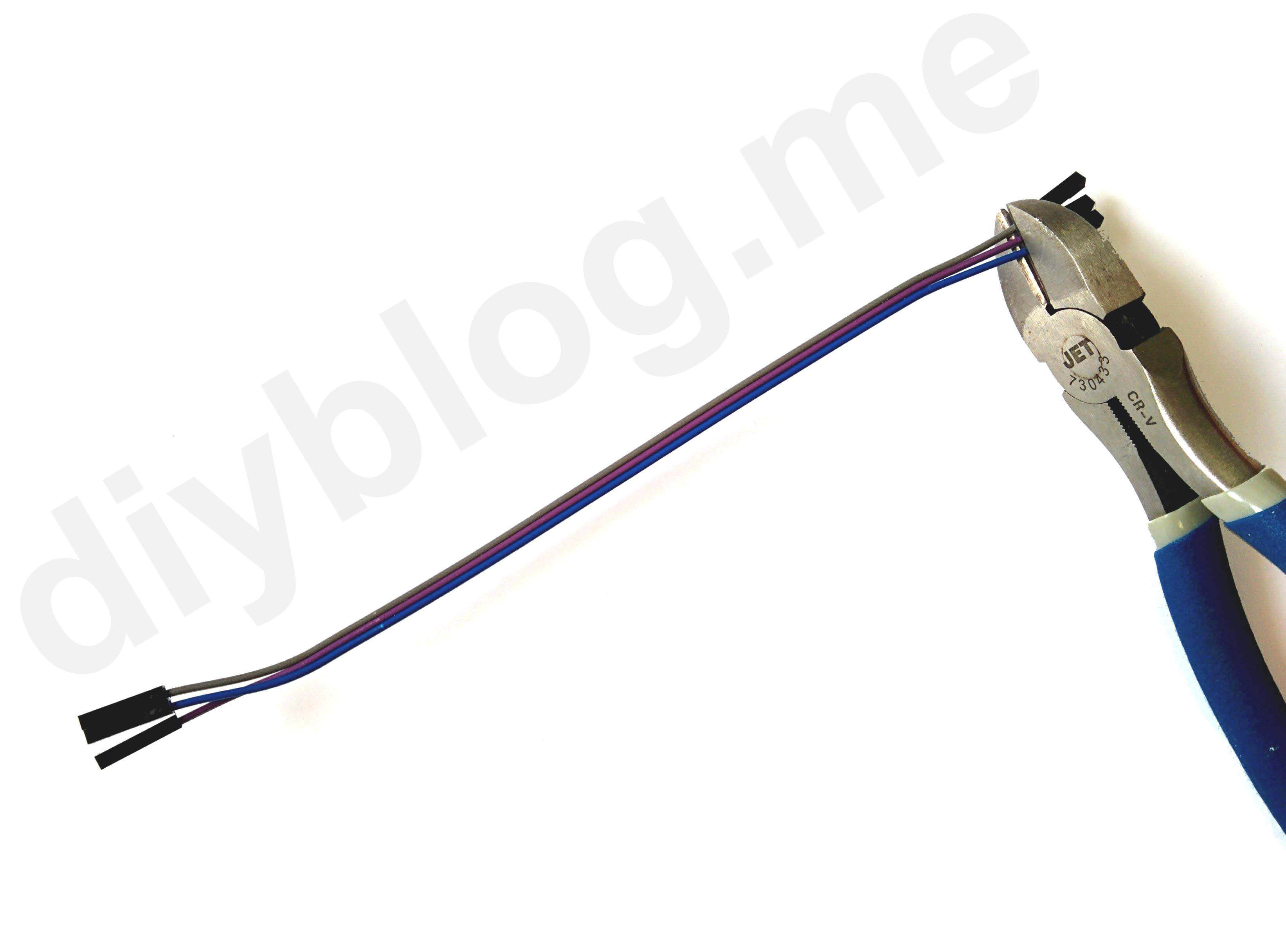
We need three female Dupont connectors shortened together for controlling both relays and supplying ground signal to the relay board. So just cut female ends from jumper wires and strip them.
Twist them all together. Make them tidy (use heat shrink or electric tape). Crimp/solder as you see fit.
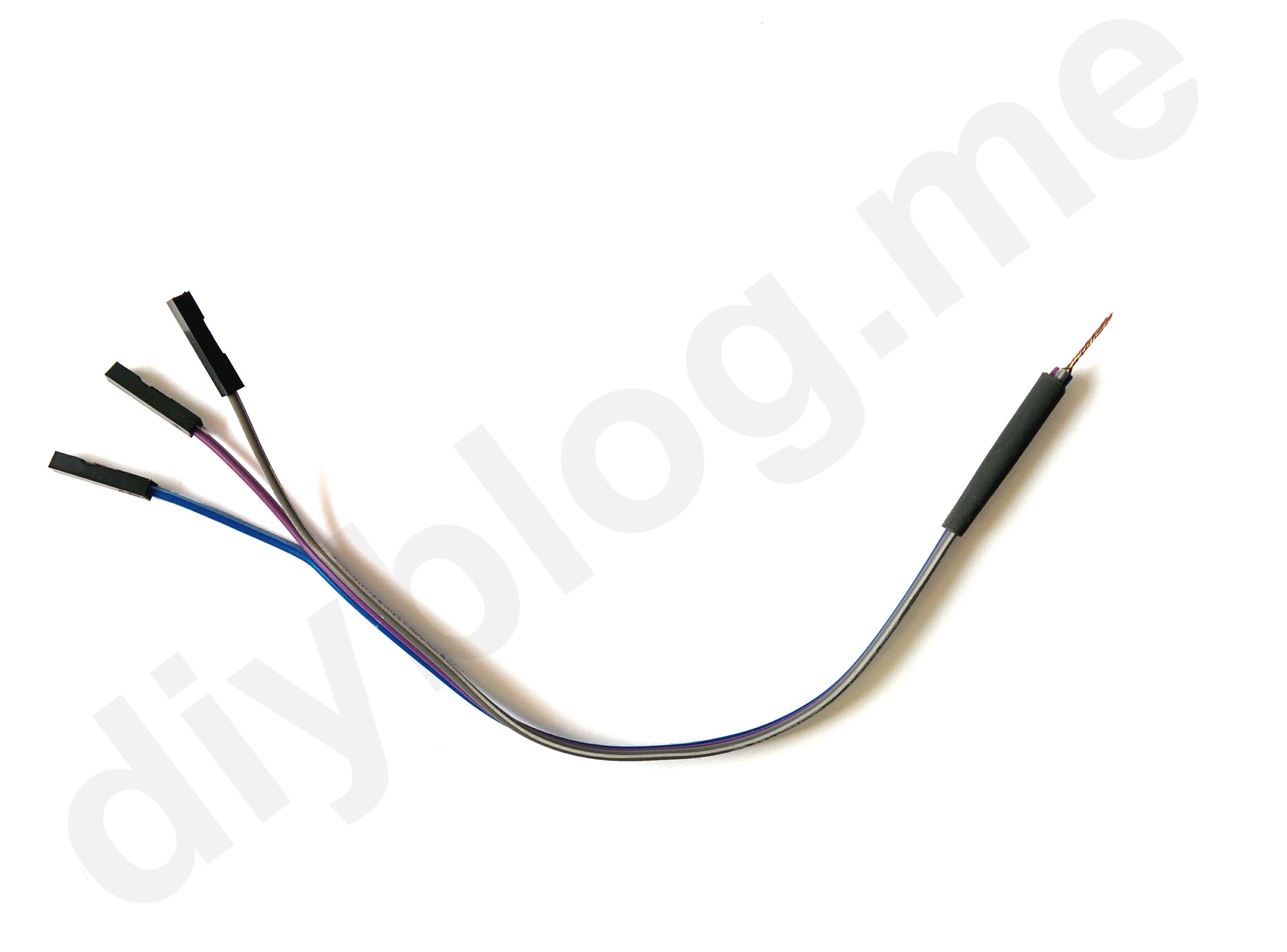
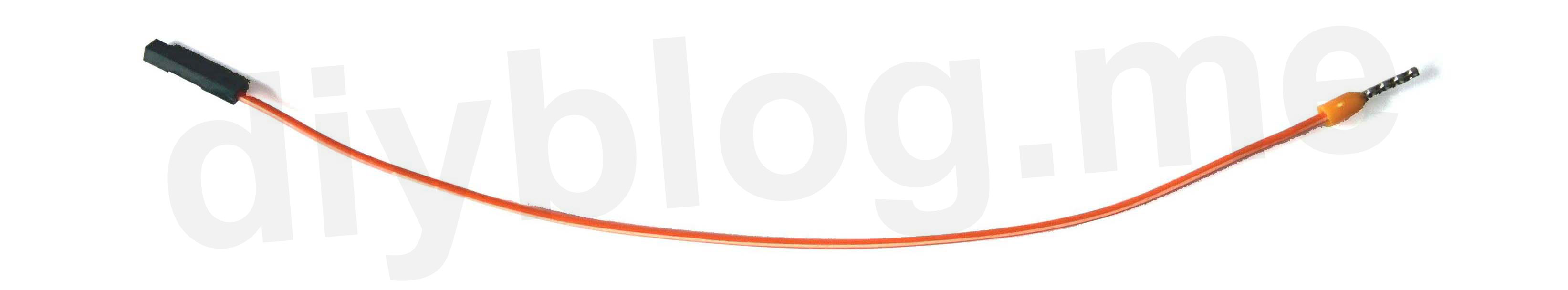
Another Dupont connector goes to the VCC pin. Simply repeat last steps!
Prepare a short jumper wire for interconnecting relays…
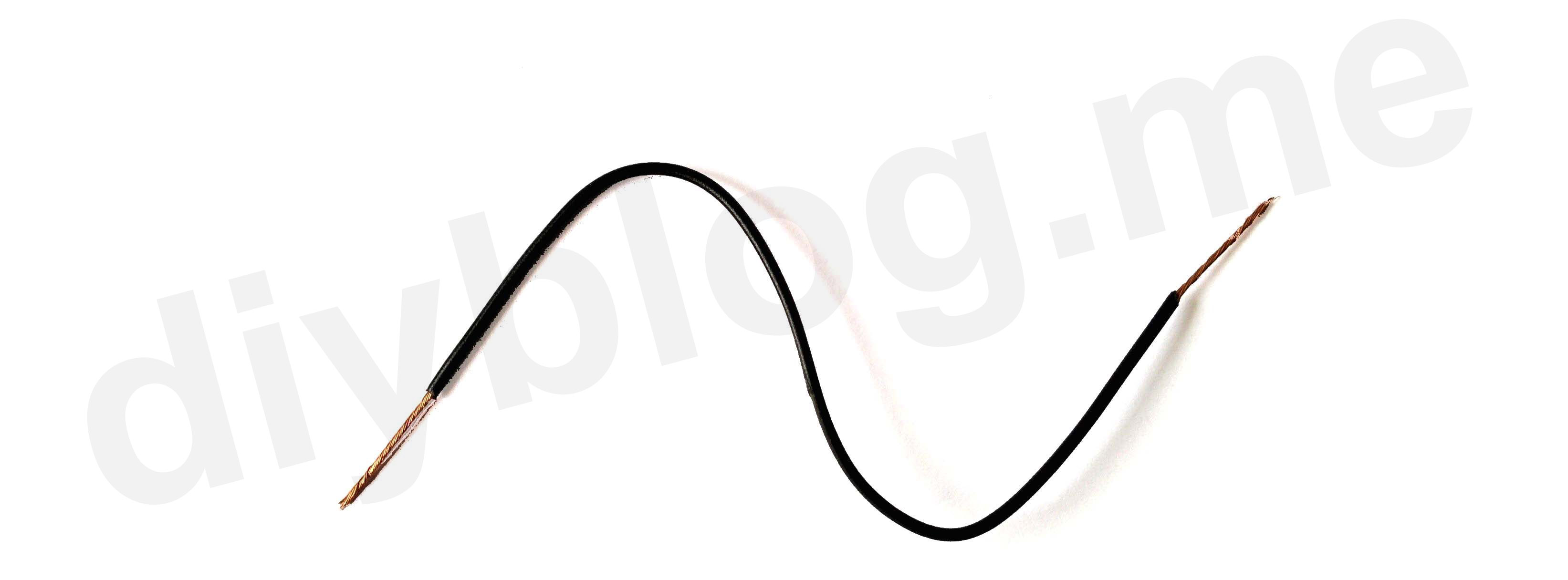
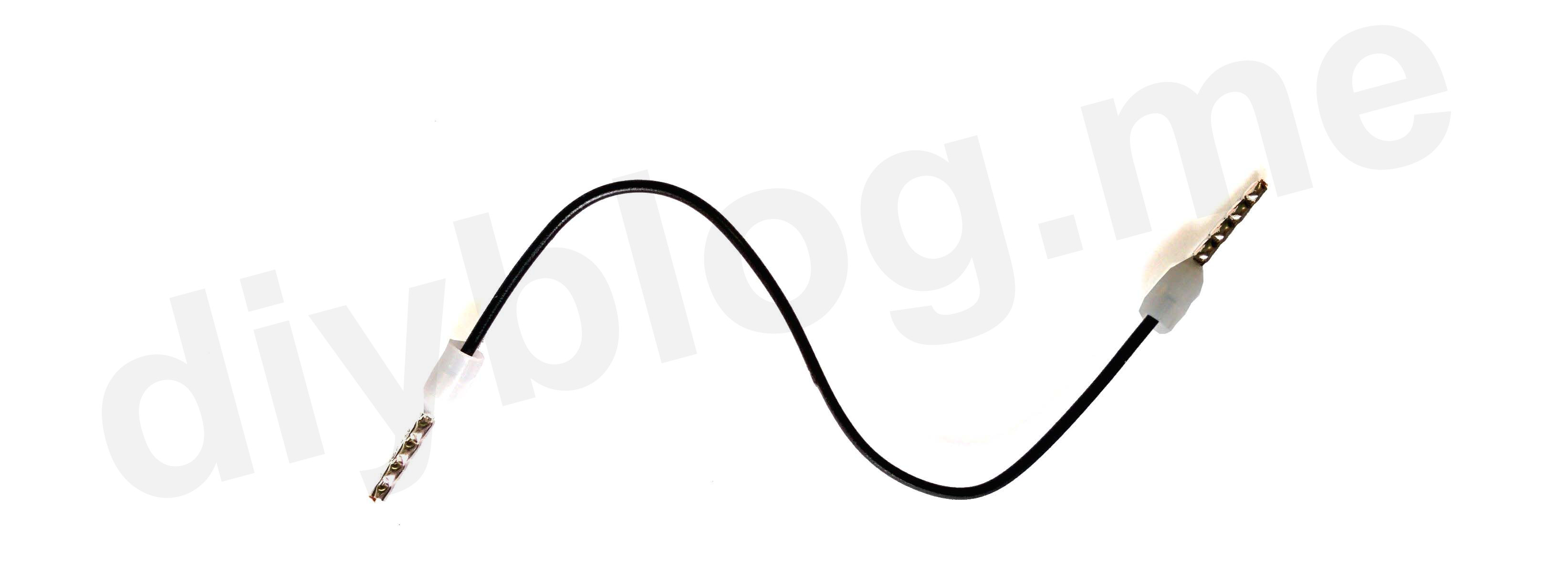
and make them two.
We’re all set to start the assembly!
Assembly
Simply follow the diagram.
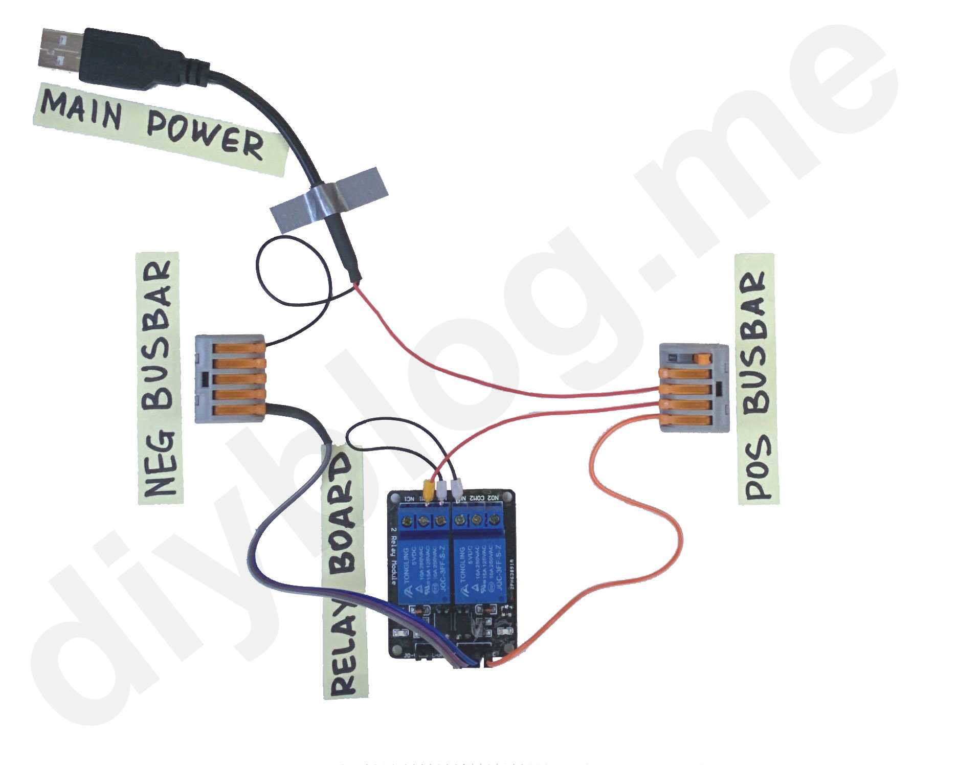
Let’s lay down both busbars (I’m using lever-nut connectors here, you can just twist the wires together) and our relay module. Connect positive busbar to VCC pin using Dupont jumper and negative busbar to IN1, IN2 and G pins using our Dupont splitter-jumper.
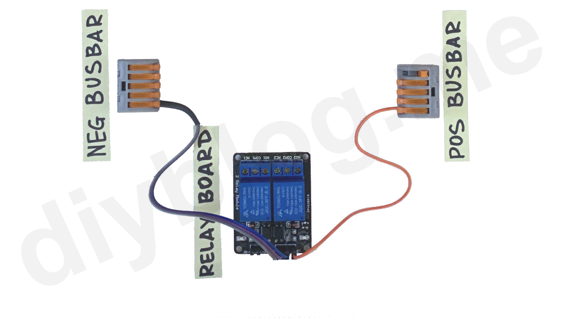
Now we’re connecting positive busbar with COM1 relay terminal using first jumper wire and shortening terminals NO1 and NC2 using the second one.
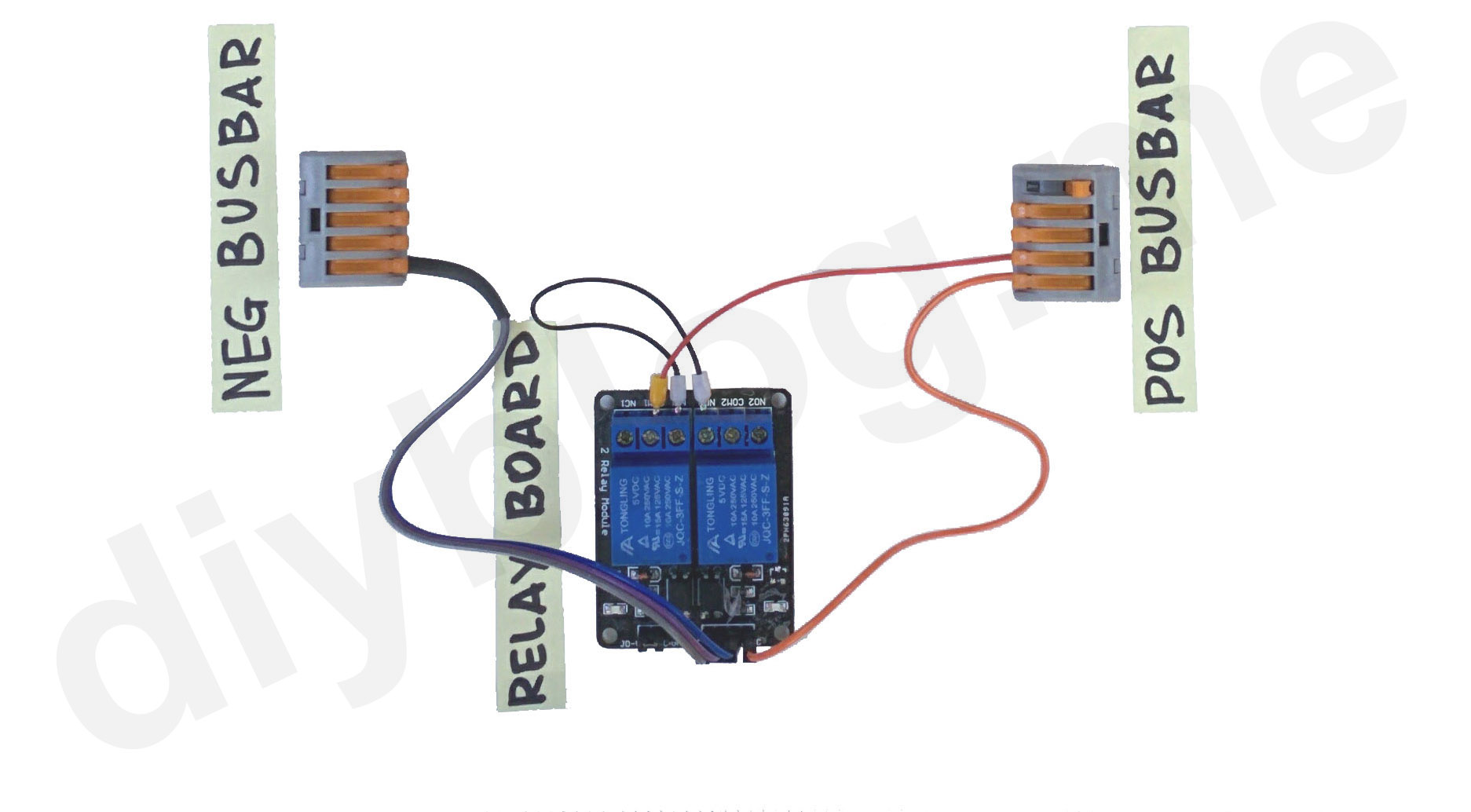
It’s time to connect various USB cables. Starting with main power cable (that’ll be connection to the wall plug power supply or 12V car adapter). Negative wire goes to negative busbar, positive wire - to positive busbar.
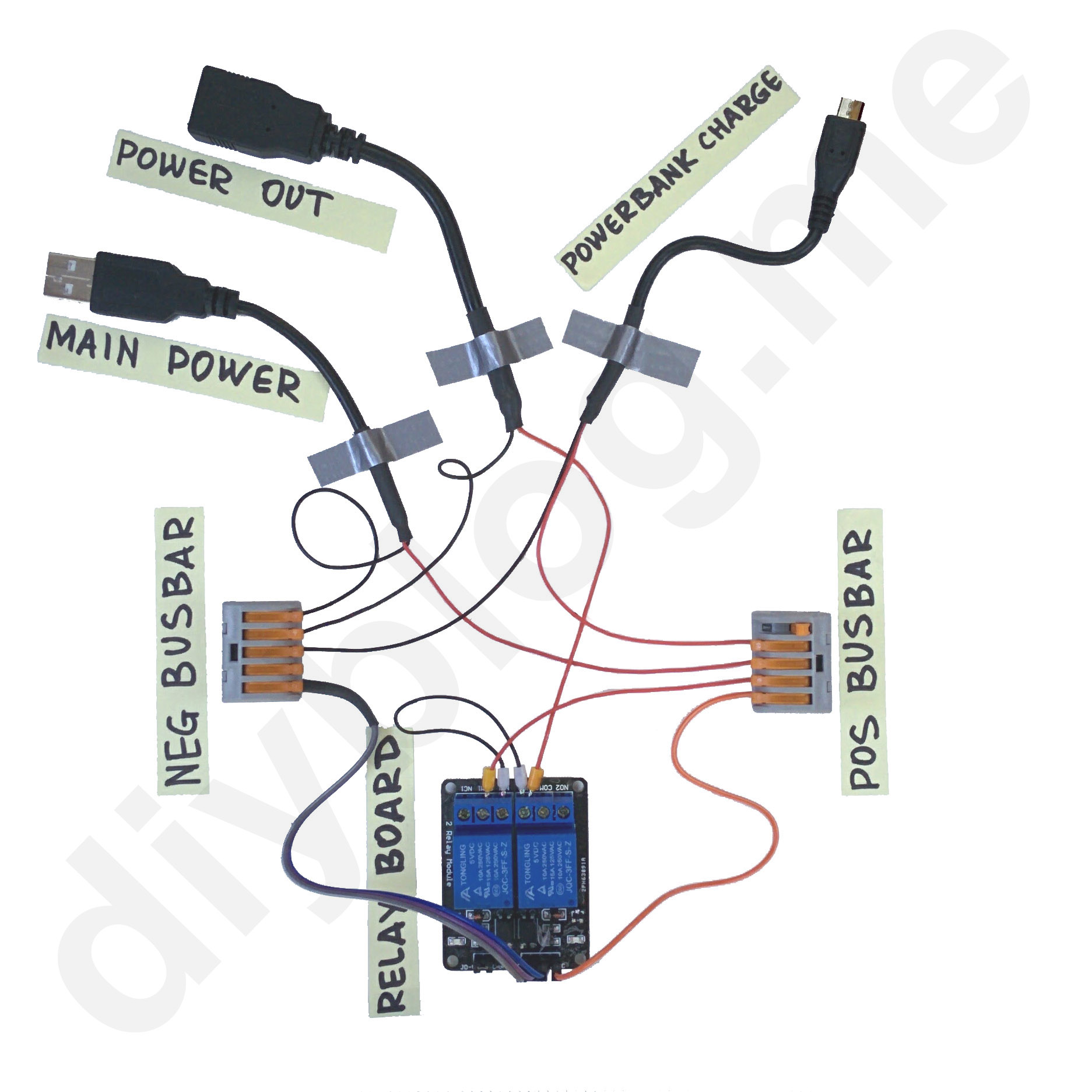
Now the power output cable (to be connected to our USB device). Negative wire goes to negative busbar, positive wire goes to NC2 terminal of the relay board (together with already connected jumper wire).

Next we are connecting charging cable for power bank (this one will keep power bank charged when there is normal power available). Negative wire goes to negative busbar, positive wire goes to positive busbar.
And the last step is to connect power bank discharge cable (this one will supply power to our USB device when normal power is not available). Negative wire goes (surprise) to negative busbar, positive wire - to COM2 terminal of the relay board.
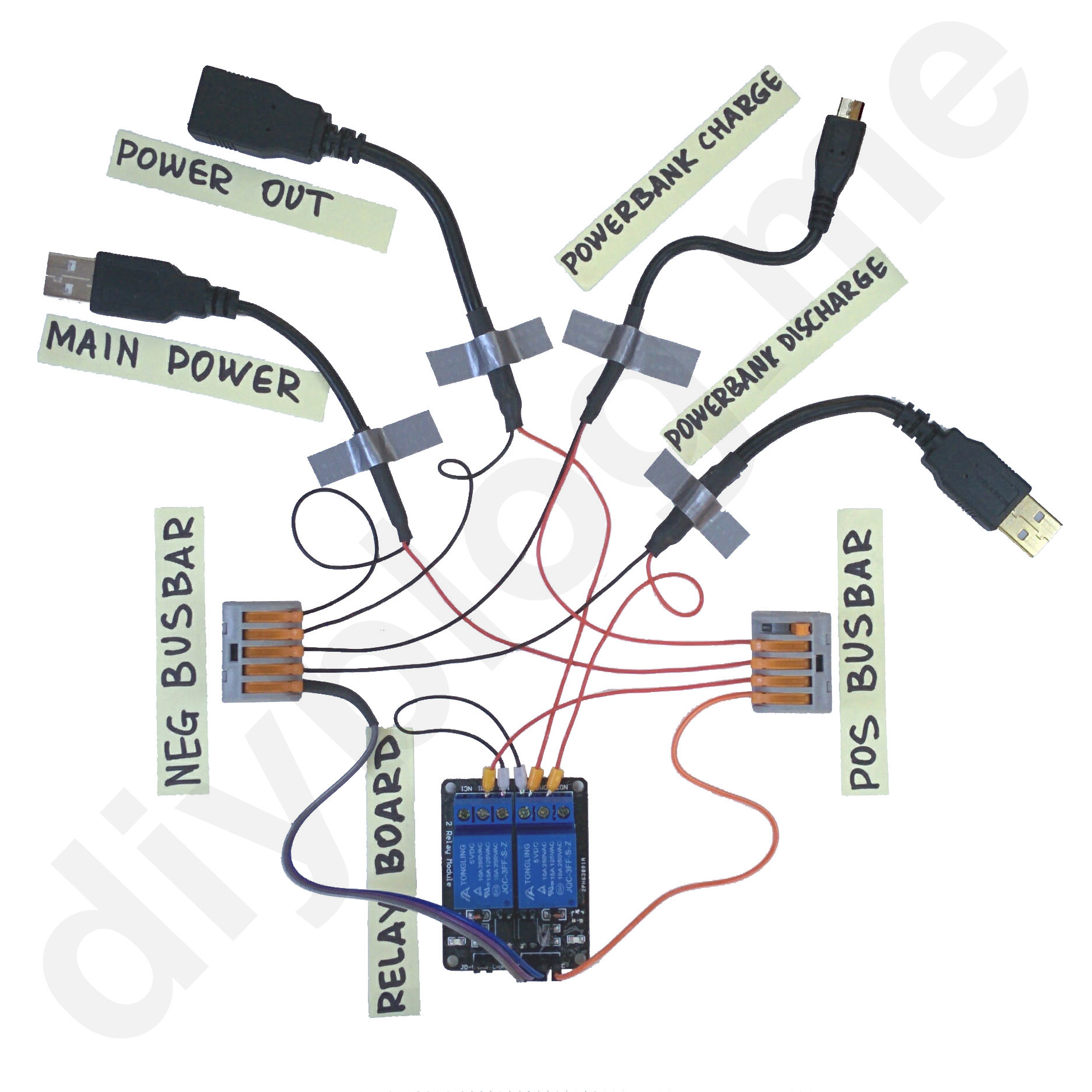
We’re done! Our very own 5V uninterruped power supply is ready to go.
Testing
I’m testing this setup here using my dash camera while connecting and disconnecting external 5V power supply to the relay (i.e. simulating a power outage). You can hear switching relay and see switching modes of power bank (IN/OUT). Power indicator on the dashcam (red LED) stays on, confirming that we achieved our goal!
Battery life
Let’s say I’m using 10,000 mAh power bank for running this dash camera. Current consumption of the camera itself varies in the range of 200 mA..400 mA when recording with the screen off. Averaging this for an hour of recording, I’ve got 315 mA.
That gives 10,000 mA*hr / 315 mA = 31.7 hr of recording. Make sure your SD card is of enough capacity :)
FAQ
- Can I simply connect charging and discharging cables directly to the power bank? No. Power banks cannot manage both charging and discharging simultaneously (unlike specialized UPS units).
- Aren’t Dupont jumper wires too thin for power applications? They are only used as signal wires for opening/closing relays (currents less than 50 mA).
- Why
IN1andIN2relay contacts are connected to the ground? This relay board is of NPN logic (active-low), thereforeIN1andIN2must be pulled to ground to activate relays.